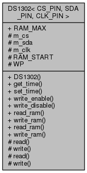
template<BOARD::pin_t CS_PIN, BOARD::pin_t SDA_PIN, BOARD::pin_t CLK_PIN>
class DS1302< CS_PIN, SDA_PIN, CLK_PIN >
GPIO based device driver for DS1302, Trickle-Charge Timekeeping Chip.
- Parameters
-
| [in] | CS_PIN | chip select board pin. |
| [in] | SDA_PIN | serial data board pin. |
| [in] | CLK_PIN | clock board pin. |
Circuit
+------------+
(VCC)---------------1-|VCC |
(GND)---------------2-|GND |
(CLK)---------------3-|CLK |
(SDA)---------------4-|DAT |
(CS)----------------5-|RST |
+------------+
References
- On-line product description, http://www.maximintegrated.com/datasheet/index.mvp/id/2685
- Datasheet, http://datasheets.maximintegrated.com/en/ds/DS1302.pdf
Definition at line 53 of file DS1302.h.
template<BOARD::pin_t CS_PIN, BOARD::pin_t SDA_PIN, BOARD::pin_t CLK_PIN>
| void DS1302< CS_PIN, SDA_PIN, CLK_PIN >::write_ram |
( |
void * |
buf, |
|
|
size_t |
size |
|
) |
| |
|
inline |
Burst write data in buffer with given size to the static memory in the device (max 31 bytes). Burst write is always from address zero(0) and includes handling of write protect.
- Parameters
-
| [in] | buf | pointer to memory block to write. |
| [in] | size | number of bytes to write (max RAM_MAX(31)). |
Definition at line 193 of file DS1302.h.
 1.8.11
